Tutorial 1
Sloping convection and rotating annulus flows
When a fluid is subject to differential heating in the horizontal direction, the resulting thermally driven circulation will tend to produce a statically stable (bottom-heavy) density distribution and, unless heat transport is extremely efficient, a temperature gradient in the horizontal direction.
This means that density surfaces will be inclined to surfaces of constant geopotential, as shown in (a) below. This is the situation, for example, in the atmospheres of the Earth and other terrestrial planets, in which polar regions are typically strongly cooled (thermal infrared emission dominates over solar heating), while the tropics experience net heating where direct solar heating is most intense. The figures below, therefore, could represent cross-sections in latitude and height through the atmosphere.
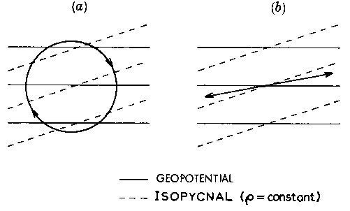
- In a non-rotating fluid, simple convective overturning will try to tilt the density surfaces to be as closely horizontal as possible.
- In a system rotating about a vertical axis, however, horizontal motion in such an overturning circulation will tend to be inhibited, because Coriolis forces deflect such motion into the zonal direction. In the absence of a zonal pressure gradient, therefore, axisymmetric geostrophic, and north–south heat transport and direct overturning, is inhibited.
- Non-axisymmetric flow, however, such as in zonally periodic waves, may be associated with non-axisymmetric pressure gradients. While such wavy flow cannot produce simple overturning motion, it can lead to significant horizontal heat transport. This may result in zonally averaged sloping trajectories resembling those shown in (b) above. If the slope of these averaged fluid trajectories lies between the horizontal and that of the isopycnals (i.e. lines of constant density), heat may be transported both upwards and horizontally, leading to a reduction in the isopycnal slope and release of potential energy. Thus, wave-like perturbations can be sustained at the expense of the potential energy generated by differential heating.
- The instability leading to these non-axisymmetric perturbations is known as baroclinic instability and the fully-developed form of these wave-like flows is sloping convection.
Sloping convection in the laboratory
The conditions leading to the formation of sloping convection can be produced relatively easily in the laboratory, in a liquid contained in the annular space between a pair of upright, co-axial, thermally-conducting cylinders (see below).
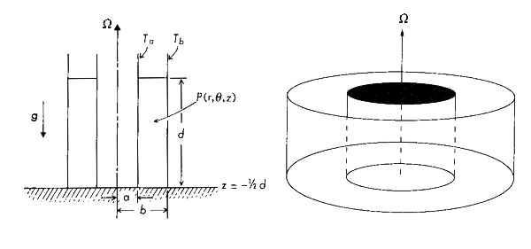
- The two cylinders are maintained at different temperatures (\(T_a\) and \(T_b\)), leading to a direct overturning circulation linking the heated (usually outer) wall with the cooled (usually inner) cylinder – somewhat like (a) above.
- If the cylinders are placed on a platform rotating about a vertical axis at angular velocity \(\Omega\), however, axisymmetric radial flow is inhibited by Coriolis forces and a significant horizontal temperature gradient will develop. Increasing \(\Omega\) actually reduces radial heat transport, because this actually takes place mainly in viscous Ekman layers along the horizontal boundaries. Thus the isopycnal slope tends to increase with \(\Omega\).
- At a certain critical value of \(\Omega\), the slope becomes too large for the fluid to sustain without the development of an instability. The flow develops non-axisymmetric perturbations which are baroclinically unstable. Such perturbations grow in amplitude, transporting heat and releasing potential energy as the slope of the isopycnals is reduced.
- The resulting flow is a form of fully developed sloping convection, and the experimental configuration above is known as the differentially heated rotating annulus. This configuration has been the subject of extensive study since the 1950s.
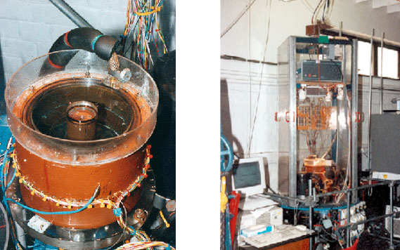
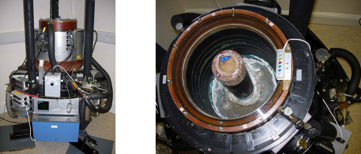
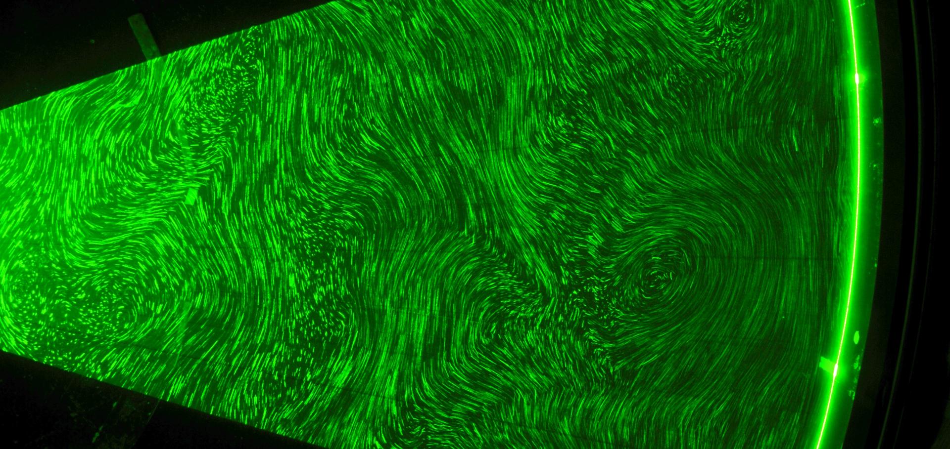
Typical experimental realisations are shown above, as developed at the UK Met Office and Oxford University.
Sloping convection flows in the laboratory
In the following pages we present in more detail various aspects of sloping convection in forms which have been studied in the laboratory: