Tutorial 1.4
Baroclinic annulus flows with internal heating
The use of direct internal heating of the fluid, in addition to conductive heating or cooling at the cylindrical side boundaries, allows greater flexibility in exploring the influence of different background thermal structure on baroclinic instability. Experimentally, internal heating may be applied by using a weak electrolyte (a dilute solution of an inorganic salt) as the working fluid and applying an alternating electric current between the inner and outer sidewall. A schematic arrangement is shown below:
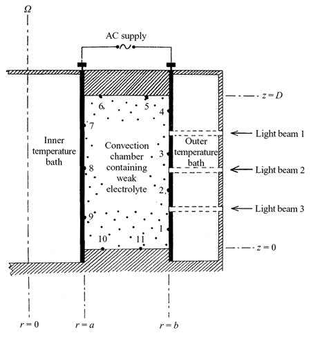
Because of the cylindrical curvature, this arrangement leads to a spatially varying heat-source term with a strength proportional to \(\frac{1}{r^2}\) – so more heating per unit volume appears near the inner cylinder than further out.
Background flow patterns
Since the working fluid is now heated in the interior of the annular channel, we are free to apply cooling, either at one – or both! – sidewalls. Where we cool at just one boundary (the inner or outer cylinder), the other may be thermally insulated (so \(\frac{\mathrm{d}T}{\mathrm{d}r}=0\)). By the thermal wind equation, \(\frac{\mathrm{d}T}{\mathrm{d}r}=0\) implies that \(\frac{\mathrm{d}v}{\mathrm{d}z}=0\). Taken together with the non-slip boundary condition at the bottom of the tank, this means that the mean azimuthal velocity \(v\) itself is likely to be zero at all heights wherever \(\frac{\mathrm{d}T}{\mathrm{d}r}=0\).
By choosing different combinations of internal heating and/or sidewall cooling at either or both cylinders, therefore, we can set up a range of different azimuthal flow patterns, all with anticyclonic shear at upper levels. Cases can include flow that is either monotonic with radius (when either the inner or outer boundary is thermally insulated), or reverses in a pair of opposing jets (when both inner and outer sidewalls are cooled). The possible flow combinations are illustrated below:
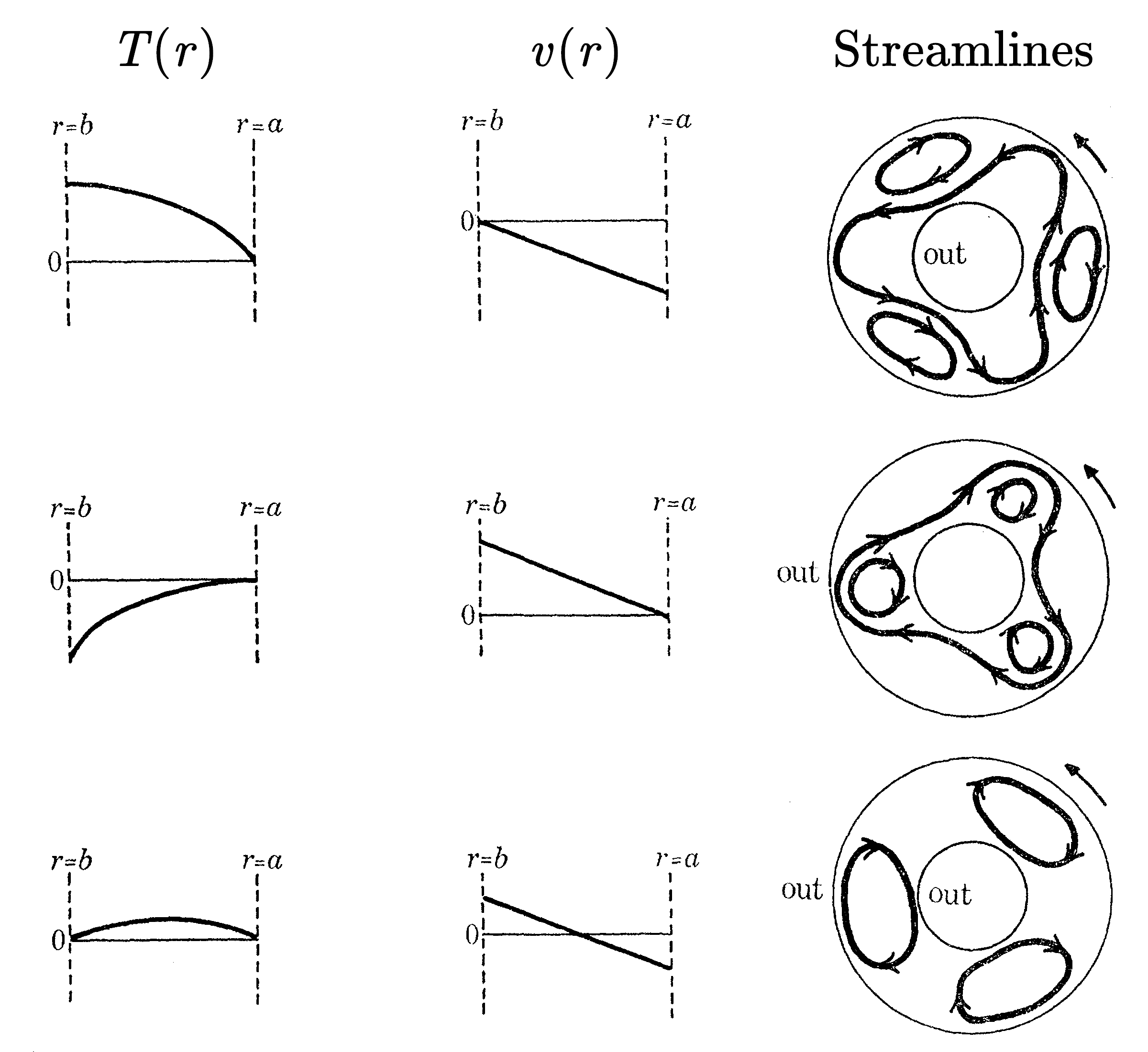
Fig. 1.4b, from Hide & Mason 1970, illustrates patterns of either axisymmetric or baroclinic wave flows, in three different combinations of heating and cooling applied at the outer (\(r=b\)) and inner (\(r=a\)) walls:
- First row: outer wall insulated, inner wall cooled
https://youtu.be/i7Uoii-8ILQ https://youtu.be/8B6JBMnHCvE - Second row: outer wall cooled, inner wall insulated
https://youtu.be/dDxgpLJVSjk https://youtu.be/6bjbRQZ4iKo - Third row: both walls cooled
https://youtu.be/AZhn3ifcTB4 https://youtu.be/G7kctSTojxg
Flow regimes
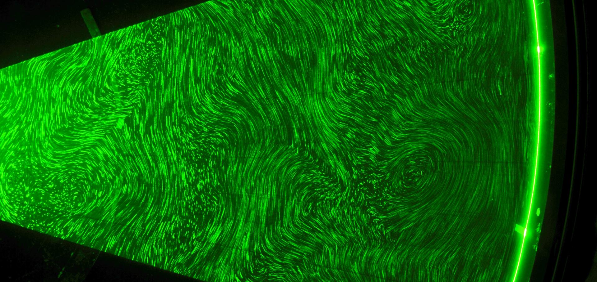
Like their more classical boundary-only heated or cooled counterparts, baroclinic waves with internal heating exhibit a wide range of different types of flow regime, depending upon the strength of heating and background rotation rate \(\Omega\). We can map the behaviour of the flow on a regime diagram as illustrated below (obtained for an internally heated flow with cooling at both sidewalls by Read, Lewis & Hide 1997).
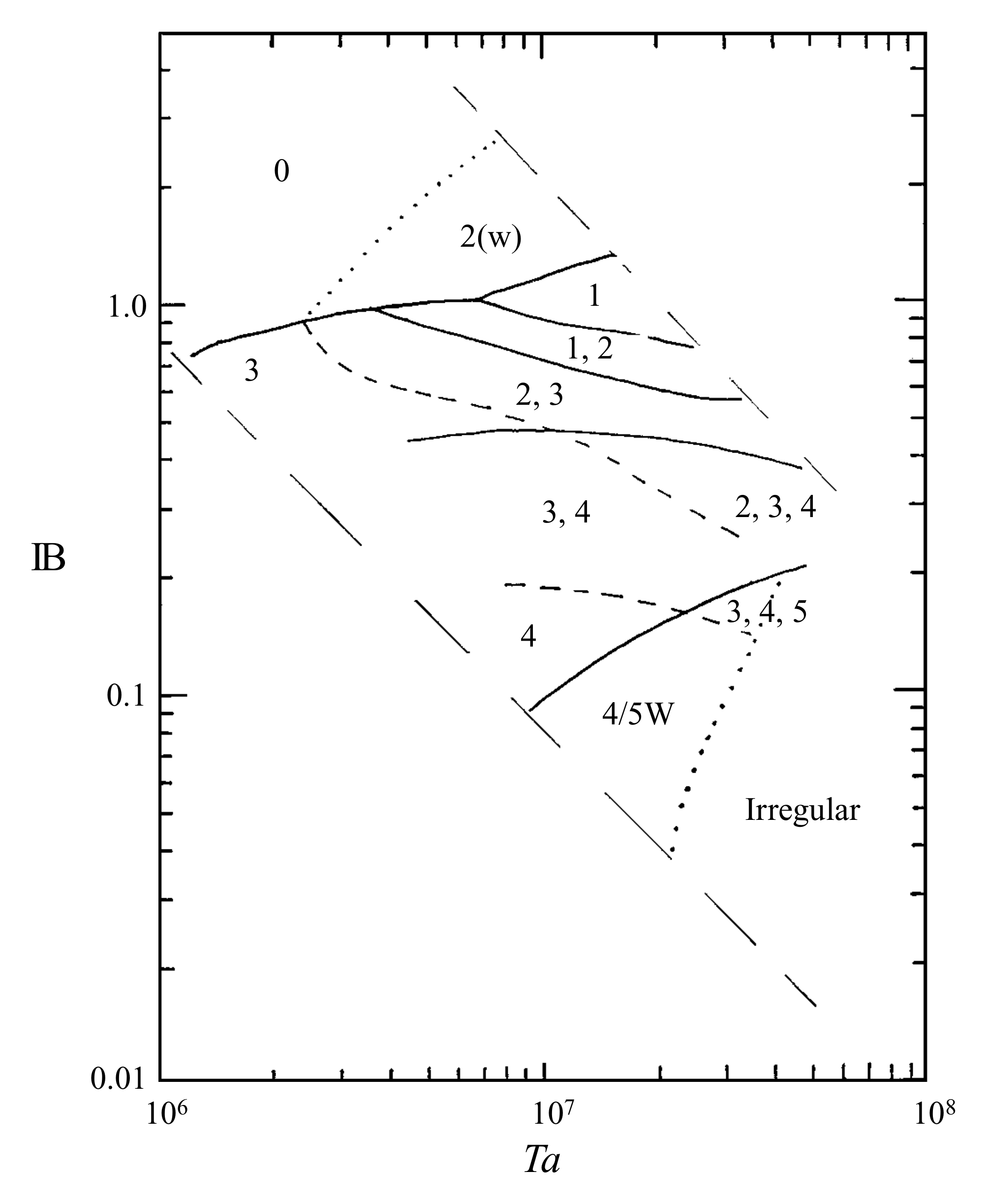
In the regime diagram above (Fig. 1.4b), numbers denote each type of wave observed in each region of parameter space. Solid lines denote well-defined boundaries observed with \(\Omega\) decreasing, dashed lines denote boundaries observed when \(\Omega\) increases, and dotted lines indicate the approximate location of less distinct transitions. Diagonal long-dashed lines indicated the edges of the domain explored in Read, Lewis & Hide 1997, corresponding respectively to power inputs of approximately \(\text{30 W}\) (lower left) and \(\text{2.5 kW}\) (upper right).
Remarks:
- Axisymmetric flow occurs at low values of \(\Omega\) for a given heating rate
- Regular, coherent waves occur at moderate values of \(\Omega\), with a tendency for higher azimuthal wavenumbers at larger \(\Omega\) and Taylor number
- Irregular, more chaotic flows occur at high \(\Omega\) and large Taylor number / small Hide number